


Server Rack Mounted Load Banks For Data Center
In order to meet the requirements of the next generation of high-density, intelligent and low pue in the data center, the corresponding load of the micro module is also evolving iteratively.
will take serious attitude to complaints of our Rata if there is any.
Product Overview
In order to meet the requirements of the next generation of high-density, intelligent and low pue in the data center, the corresponding load of the micro module is also evolving iteratively. The server rack mounted load banks is an important test tool, which realizes the simulation and replacement of L2 layer equipment (conventional server, high-density server and high-density router) in the computer room through the adjustment of heat source and air volume.
Rack mounted Load bank
Click picture for details
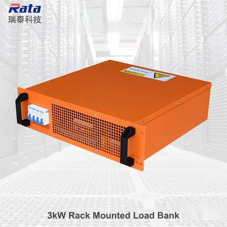
3kW Load bank
1kW resolution,MCB control,customized color and function
5kW Load Bank
500W resolution,MCB control,customized color and function
6kW Load Bank
1kW resolution,MCB control,customized color and function
7kW Load bank
1kW resolution,MCB control,customized color and function
Functions available
High Temperature Alarm
Rata supply high temperature alarm function for rack mounted load bank ensure the load bank will be working at a safety environment.
Air Volume Adjustabe
There is a knob for air volume adjust to meet different working requirement and save energey during the usage.
CFM Show
The load bank will be equipped with a LCD display meter to show the air volume.
Digital Meter
Digital meter installed to show the voltage,current,power and other data for the load bank.
Data Sheet
|
Note: all parameters are for reference only and can be customized |
|
|
Product name |
Rack mounted load bank |
|
Rated voltage |
AC230V or customized |
|
Maximum load power |
According to customer needs |
|
Load grading |
According to customer needs |
|
Load accuracy (per gear) |
±2% |
|
Connection mode |
Three input,independent control power input |
|
Insulation class |
F |
|
Air volume |
Depends on the power capacity of the load bank |
|
Cooling mode |
Forced air cooling,horizontal air discharge |
|
Control mode |
Miniature circuit breaker control |
|
Protection function |
High temperature alarm(70℃) high temperature automatic unloading(85℃) |
|
Color |
Customized |
|
Ambient temperature |
-20℃ to 50℃ |
|
Humidity |
Up to 100% |
|
Altitude |
Up to 2500m |
|
Atmospheric pressure |
86 to 106kPa |
|
Power(kW) |
Voltage(V) |
Frequency(Hz) |
Height |
Loading step |
|
3 |
220/240 |
50/60 |
3U |
0.5kW or 1000W |
|
3.5 |
220/240 |
50/60 |
3U |
|
|
4 |
220/240 |
50/60 |
4U |
|
|
4.5 |
220/240 |
50/60 |
4U |
|
|
5 |
220/240 |
50/60 |
4U |
|
|
6 |
220/240 |
50/60 |
6U |
|
|
7 |
220/240 |
50/60 |
6U |
|
|
8 |
220/240 |
50/60 |
8U |
|
|
9 |
220/240 |
50/60 |
8U |
|
|
10 |
220/240 |
50/60 |
8U |
|
|
12 |
220/240 |
50/60 |
12U |
Connection Procedure
■ Ensure the power source to be tested is compatible with the load bank operating voltage.
■ Do not attempt to operate the load bank above the maximum operating voltage.
■ Check the power source is isolated before connecting to the load bank.
■ Check the power isolator circuit breaker is in the OFF position.
■ Check the control switches is in the OFF position.
■ Connect the power cable to the power source and earth where practical.
■ Check the AC output cable connections are secure.
Operating Instructions
>Operators should read the SAFETY CONSIDERATIONS and CONNECTION PROCEDURE before carrying out the following operating instructions.
■ Ensure the power switch is in the OFF position.
■ Ensure all selector switches are in the OFF position.
■ Turn on the power switch and ensure the fan rotates correctly without restrict the airflow.
■ Switch on the appropriate load current channels to the required load current.
■ At the end of the test,switch off all the load current switches.
■ Do not switch off the power switch or the power source.
■ Ensure the fan is kept running for 5 minutes to cool the resistor elements.
■ When the resistor elements are cold,switch off the power and switch off the power source and disconnect the cable from the power source.
has complete quality control system and good after-sales service.