


Permanent Installed Load Bank
Rata 5000kW permanent load bank improves the quality of the resistance tube by strictly controlling the manufacturing process of the resistance tube, and improves the design of the resistance tube.
Manual inspection and equipment testing both have been carried out to ensure that the product is 100% qualified.
PRODUCT OVERVIEW
Rata 5000kW permanent installed load bank improves the quality of the resistance tube by strictly controlling the manufacturing process of the resistance tube, and improves the design of the resistance tube. In addition, according to the requirements of customers, the intelligent control software that can put the inductor into operation enables the resistance tube to be used in a balanced manner, prevent the aging of various components, and truly achieve the purpose of prolonging the overall life of the load bank. Therefore, Rata 5000kW permanent load can fully meet the bank's long-term use
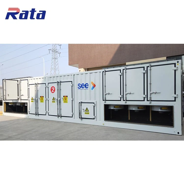
PRODUCT PICTURE
PRODUCT PICTURE
APPLICATION SCENARIO
PARTIAL PARAMETERS
|
Note: all parameters are for reference only and can be customized |
|
|
Product name |
permanent load bank |
|
Specifications |
R5000kW/10.5kV/400V/50Hz |
|
Formation |
One load bank(Including dry resistance load, electrical control components, measurement and control system) |
|
Load step |
According to customer needs |
|
Load connection |
Copper bar |
|
Resistor |
Each resistance element: insulation impedance DC1000V/100MΩ above Withstand voltage ac 2000v for 5min Resistance error of each resistance tube:±3% |
|
Load control |
Local manual control, local automatic control or remote automatic control can be selected |
|
Loading accuracy |
Less than or equal to 3% |
|
Three phase balance |
Unbalance degree less than or equal to 3% |
|
Minimum step |
1kW |
|
Working mode |
Continuous work |
|
Load protection |
Short circuit, overcurrent, high temperature, fan fault protection |
|
External power |
TN-C,380V/50Hz |
|
Cooling mode |
Forced air cooling, side air outlet or top air outlet |
|
Insulation class |
F |
|
Measurement accuracy |
The display accuracy is 0.5,the sampling accuracy is 0.2 |
|
Electrical parameter display |
Three phase voltage, three-phase current, frequency, power, etc |
|
Voltage rising mode |
Realized by transformer |
|
Load expansion |
Parallel expansion of multiple load containers |
|
Standard |
Meet international standard, ship standard, military standard and telecommunication standard |
|
Transport |
The load bank has a load-bearing lifting hole, which meets the requirements of long-distance transportation |
|
Color |
Customized |
|
Ambient temperature |
-20℃ to 50℃ |
|
Humidity |
Up to 100% |
|
Altitude |
Up to 2500m |
|
Atmospheric pressure |
86 to 106kPa |
MORE SPECIFICATIONS
|
Note: all parameters are for reference only and can be customized |
||||
|
Power(kW) |
Voltage(kV) |
Frequency(Hz) |
Size(mm,L*W*H) |
Weight(Kg) |
|
Low voltage |
||||
|
100 |
0.4 |
50 |
1100*900*1000 |
320 |
|
200 |
0.4 |
50 |
1350*1100*1100 |
450 |
|
300 |
0.4 |
50 |
1500*1200*1200 |
650 |
|
400 |
0.4 |
50 |
1700*1500*1500 |
830 |
|
500 |
0.4 |
50 |
1700*1600*1600 |
950 |
|
600 |
0.4 |
50 |
1800*1600*1600 |
1150 |
|
800 |
0.4 |
50 |
1900*1800*1700 |
1900 |
|
1000 |
0.4 |
50 |
2300*1700*2100 |
2100 |
|
1200 |
0.4 |
50 |
2500*1800*2200 |
2300 |
|
1500 |
0.4 |
50 |
2500*1860*2300 |
2600 |
|
1800 |
0.4 |
50 |
3000*2000*2300 |
4000 |
|
2000 |
0.4 |
50 |
3000*2000*2300 |
5000 |
|
2500 |
0.4 |
50 |
4000*2438*2500 |
6000 |
|
3000 |
0.4 |
50 |
6000*2438*2500 |
7000 |
|
Medium voltage |
||||
|
1000 |
6/10.5 |
50/60 |
3000*2438*2500 |
3500 |
|
1200 |
6/10.5 |
50/60 |
4000*2438*2500 |
3900 |
|
1500 |
6/10.5 |
50/60 |
4000*2438*2500 |
4500 |
|
1600 |
6/10.5 |
50/60 |
5000*2438*2500 |
5000 |
|
1800 |
6/10.5 |
50/60 |
5000*2438*2500 |
6500 |
|
2000 |
6/10.5 |
50/60 |
6000*2438*2500 |
7500 |
|
2200 |
6/10.5 |
50/60 |
6000*2438*2500 |
8000 |
|
2500 |
6/10.5 |
50/60 |
6000*2438*2500 |
10000 |
|
3000 |
6/10.5 |
50/60 |
7000*2438*2500 |
12000 |
|
4000 |
6/10.5 |
50/60 |
8000*2438*2500 |
14000 |
|
5000 |
6/10.5 |
50/60 |
9000*2438*2500 |
15000 |
|
6000 |
6/10.5 |
50/60 |
12000*2438*2500 |
16000 |
|
7000 |
6/10.5 |
50/60 |
12000*2438*2500 |
17000 |
|
8000 |
6/10.5 |
50/60 |
12000*2438*2500 |
18000 |
DESIGN DRAWINGS
TRANSPORT AND INSTALL
The top four corners of the load bank are provided with lifting holes and the bottom four corners are provided with rollers to facilitate loading, transportation and mobile installation.
BUSBAR INSTALLATION SPECIFICATION
(1)Check the quality of bus and its accessories, and do not install unqualified ones.
(2)Fasteners for bus connection shall be galvanized bolts, nuts and washers of national standards.
(3)The contact surface shall be kept clean and coated with neutral Vaseline or compound grease.
(4)When the bus is placed horizontally, the through bolt shall be threaded from bottom to top. In other cases, the nut shall be placed on the maintenance side, and the bolt length should expose 2 to 3 threads of the nut.
(5)There shall be washers on both sides of the bolt, there shall be a clear distance of more than 3mm between the washers of adjacent bolts, and the nut side shall be equipped with spring washers or lock nuts.
(6)The bolt shall be stressed evenly without additional stress on the electrical terminal.
(7)The contact surface shall be closely connected with 0.05 mm × Check with a 10mm feeler gauge. If the bus width is 60mm or more, 6mm shall not be inserted, and if the bus width is less than 60mm, 4mm shall not be inserted.
(8)The fixing between bus fixing hardware and post insulator shall be flat and firm, and the bus supported by it shall not be subjected to additional stress.
(9)When the bus working current is greater than 1500 a, the fixed fittings or other supporting fittings of each phase AC bus shall not form a closed magnetic circuit, otherwise non-magnetic fixed fittings or other measures shall be adopted according to the design regulations.
(10)When the bus is placed horizontally, the upper pressing plate of the bus support splint shall maintain a gap of 1 to 1.5mm with the bus. When the bus is placed vertically, the upper pressing plate shall maintain a gap of 1.5 to 2mm with the bus.
(11)The fixed dead center of the bus on the post insulator shall be located in the full length of the bus or the midpoint between two bus compensators.
(12)The bus bar fixing device shall be free of significant edges and corners to prevent tip discharge.
(13)A gap with the same thickness shall be maintained between multiple rectangular buses, and there shall be a gap of more than 3mm between the gaskets of two adjacent bus gaskets, which shall not touch each other.
(14)The support must be firmly installed, the bus shall be correctly placed according to the section diagram, phase sequence, number, direction and mark, and the longitudinal clearance of each phase shell shall be evenly distributed.
(15)The inner and outer walls of the bus and insulators must be wiped clean, and there shall be no residue in the shell.
HONORARY QUALIFICATION
Since its establishment, Rata has obtained 16 utility model patent certificates and 8 computer software copyright registration certificates, and has been recognized as a national high-tech enterprise.
The product has obtained plentiful related quality guarantee certifications and meets the quality standards of many countries.